News | company news | Aug 27,2024
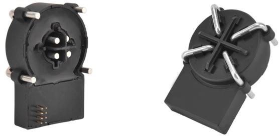
HYCA series leakage transformer
The international standard “IEC62752-2016” was officially release in 2016, and the functions and roles of IC-CPD are specifi in the standard. In 2018, the “IEC 62955” standard was released. In both standards, Type B residual current detection has become an important function. Residual current detection also becomes a mode 2 charging line, charging pile standard accessory. Yueqing Heyi Electric Co., Ltd. launched the HYCA series of B-type sensors fully meet the above standards.
What is Type B leakage transformer?
The HYCA series Type B leakage current sensor is designed to detect leakage current in alternating current systems. In electric vehicle charging stations or charging piles, this sensor is one of the important components to ensure safe charging.
The Type B leakage current sensor is characterized by the ability to detect all types of current leakage, including sine wave, non-sine wave, and DC current components. This is important for electric vehicle charging because the electric system of an electric vehicle may contain both DC and AC components, and in some cases there may be non-sinusoidal waveforms.
In the charging pile, the Type B leakage current sensor usually works with the residual current Action Protector (RCD), which cuts off the power supply to prevent electric shock once an abnormal current leak is detect.
Type B leakage current sensor used in charging piles has the following advantages:
1.The accuracy requirement of 1mA in the whole temperature zone provides a better choice for the development of leakage protection of charging piles.
2.The solution covers not only the performance indicators of the current Type A or Type A+6mA_AC.
3.It can be used with B-type leakage current sensor in three-phase AC charging pile.
The performance indicators of Type B leakage current sensor mainly include the following points:
1.Frequency range: The frequency range of Type B leakage current sensor is DC ~ 1 kHz.
2.Analog output: Type B leakage current sensor optional analog output.
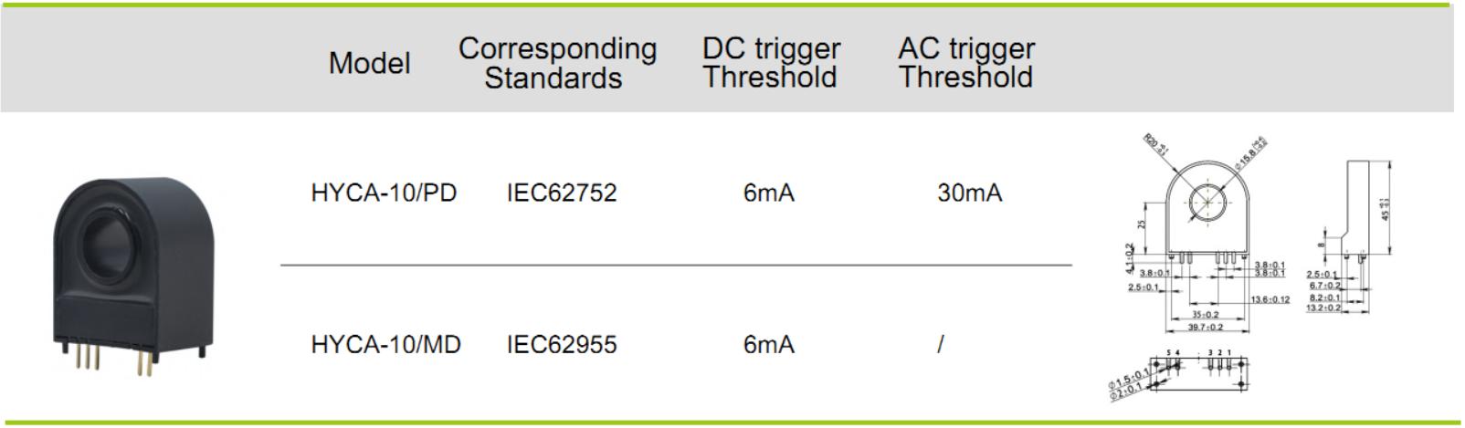
3.Digital output: Type B leakage current sensor supports DC 6mA and AC 30mA digital output.
4.Load current on the primary side: The load current on the primary side of the Type B leakage current sensor is 40 A and can be extended to 100 A.
5.Standard certification: Type B leakage current sensor complies with IEC 62752 and IEC 62955 standards.
Other indicators of the Type B leakage current sensor include:
1.Input range: This indicator defines the range of current that the sensor can accept. For example, some Type B leakage current sensors may have an optional input range of 0~500mA, such as 0~10mA, or 0~20mA.
2.Accuracy level: This refers to the degree of accuracy of the sensor, usually expressed as a percentage. For example, some Type B leakage current sensors may have an accuracy class of ≤1.0%.f.s.
3.Linearity: This refers to the linear relationship between the sensor reading and the actual current value. A good linearity means that the error between the reading and the actual current value is small. For example, some Type B leakage current sensors may have a linearity better than 0.2%.
4.Response time: This refers to the time interval between the sensor receiving the current signal and generating the output signal. For example, some Type B leakage current sensors may have a response time of less than 200ms.
5.Offset voltage: This refers to the value of the output voltage deviation from zero when the input is open under normal working conditions. For example, the offset voltage of some Type B leakage current sensors may be ≤20mV.
6.Temperature characteristics: This refers to the relationship between the change in the sensor output and the change in temperature. The temperature characteristics of some Type B leakage current sensors may be ≤150PPM/ ° C (0~50 ° C).
7.Power consumption of the whole machine: this refers to the power consumed by the sensor under normal working conditions. For example, the overall power consumption of some Type B leakage current sensors may be less than 30mA.
8.Isolated voltage resistance: This refers to the isolation voltage resistance between the sensor input, output and the housing. For example, the isolated voltage withstand of some Type B leakage current sensors may be AC2.0KV/min*1mA between input/output/housing.
9.What are the characteristics of Type B products?
Precise operating thresholds
A variety of installation methods
Wide operating temperature range: -40℃~105℃
It can be applied to power systems up to 1000V
Type B leakage transformer
What are the principle characteristics of Type B products?
The structure principle of the leakage protector is shown in the following figure.

A– Residual current trip device, R1– Ground resistance for power grounding
B-mechanical device, T-experimental device, E-electronic signal amplifier, RCT-residual current transformer
R2- Ground resistance of the working ground
The grid wire passes through the magnetic core of the RCT, and the RCT detects the phasor sum of the current of the protected line. Under normal circumstances, the phase currents are balance, and the sum of the primary side current I through the RCT is equal to zero, which is known by Kirchhoff’s current law

In this way, the sum of the magnetic flux Φ generated by the working current of each phase line in the ring core of the current transformer is also zero, that is
![]()
When an electric shock or other ground leakage fault occurs, the phasor sum of each phase load current (including neutral line current) passing through the primary side of the current transformer is no longer zero due to the existence of leakage current

consequently.
![]()
The working principle of RCT is shown in Figure 2.

Figure 2. Working principle of RCT
N1-RCT primary winding turns; N2-RCT and the number of turns of this winding; I1– leakage current of the primary loop, I2– current of the secondary loop; E2– inductive electric type of secondary circuit;
Z2– Impedance of the secondary circuit
Induce potential E2 is generate in the secondary side coil of RCT under the action of alternating flux ΦΔ, and an induce current IΔ is generated in the secondary loop which is proportional to the leakage current. The greater the leakage current, the greater the secondary winding induce potential E2, the relationship between the two, that is, the working characteristics of the transformer is shown in Figure 3. Where, curve 1 shows the no-load characteristic of the transformer when the secondary winding is open. It can be seen that the induce potential E2 on the secondary side is very small at the beginning, and only when the primary leakage current I1 increases to a certain value, E2 has an obvious output. After that, with the increase of I1, E2 keeps increasing and changes approximately linearly. When I1 reaches a certain value, the change of E2 tends to be slow or even downward, and the linearity becomes worse, which is caused by the magnetic core entering the saturation zone. Therefore, the appropriate secondary load impedance should be select to ensure that the magnetic core works in the linear segment and avoid magnetic saturation of the magnetic core. Curve 2 shows the load characteristics under the working state of the trip device. Due to the demagnetization of the secondary load current, the magnetic core becomes less saturated, and E2 becomes relatively smaller under the same leakage current condition.
Figure 3

Equilibrium characteristic
The offset of conductor in the core and the Angle of head and tail of spiral core are the two main factors that affect the balance characteristics of current transformer. The influence on the balance characteristics of the transformer is analyze by analytical calculation and numerical simulation, and the correctness of the theoretical analysis is verified by experiments. The results show that under the condition that the Angle of the CT core is 0° and the wires passing through the CT core are evenly distribute in the center of the magnetic core and magnetic shield is install on the core, the magnetic core has good balance characteristics and the device will not misoperate.
What are the application areas?
Dc, AC leakage current detection
Suitable for new energy charging pile leakage detection
Internal installation effect of DC charging pile
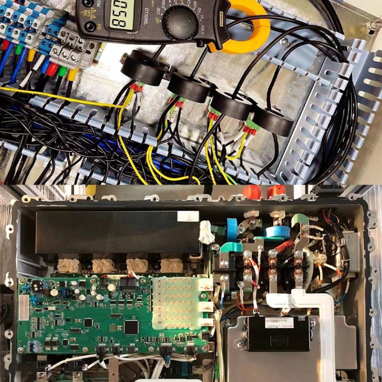
Type B leakage transformer
What are the installation methods?
(1) Vertical installation: HYCA-10/(PD, MD)
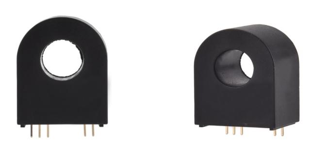
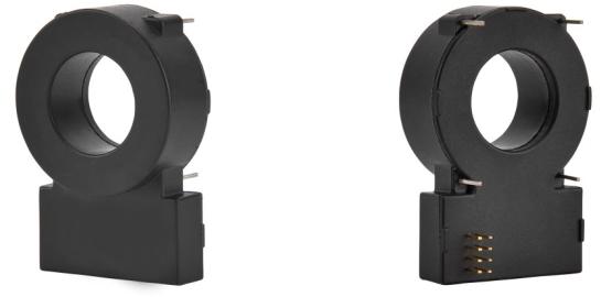
(2) Horizontal installation input throughline: HYCA-03/(PD, MD)

(3) Horizontal installation input pin type: HYCA-01/02/05
 How to choose the correct model?
Type B leakage vertical: HYCA-10/PD, HYCA-10/MD
Type B leakage horizontal input line: HYCA-03/PD, HYCA-03/MD
Type B leakage horizontal input pin type: HYCA-01/HYCA-02/HYCA-05
--- END ---
COPYRIGHT © HEYI ELECTRICS SOLUTION


