News | company news | Apr 15,2025
How to select the main technical parameters of current transformers – ratio and accuracy
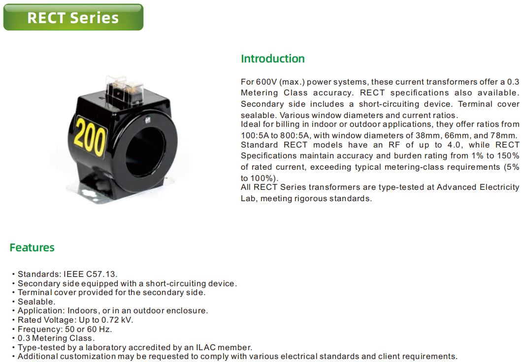
Current transformer is a unique transformer designed to convert high current into standard low current. It plays a key role in meters, measuring instruments and relays, not only expanding the measurement range of meters, but also helping to improve the reliability and safety of circuits. Its wiring method is also quite unique. The main coil is connected to the main circuit, while the coils of the secondary connected instruments and relays together form a complete circuit.
When selecting a current transformer, the following six key factors should be considered:
1.Rated primary voltage: This is usually determined by the nominal voltage of the power system. Although in theory it is possible to use a high voltage current transformer in a low voltage system, for example, a 10kv current transformer in a 6kv system, other factors must be considered in the actual selection.

2.Main current level: It should be selected according to the rated current level specified in GB1208. If it is not possible to directly select the main current of the specified level, the following measures can be taken:
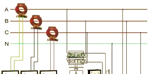
When the transformation ratio requirements of the protection circuit and the measurement circuit are different, a current transformer with a secondary winding tap can be selected, or a current transformer with different transformation ratios can be obtained by changing the primary tap. There are usually two connection methods: series and parallel.
For the measurement circuit, if a special-purpose current transformer is required, you can choose Class S, which can maintain accuracy within the rated current range of 10~110%.
3.Rated secondary current: usually 1A or 5A. The following principles should be considered when selecting:
When conditions permit, such as when building a new power plant or substation, it is recommended to use a rated secondary current of 1A.
If the installation of the transformer is conducive to the selection of 5A, or the original TA in the expansion project is 5A, and there are some occasions where the secondary open-circuit voltage of the TA needs to be reduced, the rated secondary current of 5A can be selected.
In a plant or station, 1A and 5A rated secondary currents can be selected at the same time to meet different needs.
4.Regarding the correct level and temporary properties of current transformers, we will elaborate in detail in subsequent topics.
5.The number of cores of current transformers is divided into two categories: one is single-core type, which has only one primary winding and secondary winding, which is the design of most low-voltage current transformers; the other is multi-core type, which has one primary winding and two or more secondary windings, each secondary winding is configured according to its specific purpose. For example, energy metering instruments and measuring meters can share one secondary winding if the accuracy requirements are met.
6.The structural types of current transformers include oil-immersed, resin-injected and SF6 current transformers. When choosing, we usually focus on two technical parameters: transformation ratio and accuracy.
7.Transformation ratio
The rated current value of the secondary side of the current transformer is usually set to 5A or 1A, with 5A being the more common choice. When measuring current transformers, commonly used ratios include 5/5, 10/5, 15/5, etc. These ratios can meet different measurement requirements. However, how to accurately select a suitable current transformer ratio is a problem that needs to be considered based on actual conditions.
The “Design Specifications for Electrical Measuring Instruments for Power Installations” clearly states that for pointer-type measuring instruments, the selection of the measuring range should ensure that the rated value of the power equipment is at the 2/3 position of the instrument scale. Based on this specification, we can use the following formula to select the appropriate current transformer ratio N:
In this formula, I represents the maximum load current of the circuit, and 0.7 means that under the maximum load current, the current value displayed by the meter should be 70% to 5 of the secondary rating. Next, we select the corresponding current transformer ratio according to the calculated transformation ratio N. For example, when I is 50A, the N calculated by the formula is 14.29, so we can choose a transformer with a 75/5 ratio.
Accuracy considerations
The precision of the current transformer, also often referred to as accuracy, is an important indicator of its performance. Since the current transformer has proportional error and angle error, the problem of precision is inevitable. It is worth noting that the accuracy of the converter is numerically consistent with the percentage of its ratio error limit. For example, the maximum proportional error of a current transformer with a grade of 0.5 is controlled within 0.5%. In addition, measuring transformers are usually divided into different grades such as 0.1, 0.2, 0.5, 1, 3, and 5, while protection transformers are mainly divided into 5P and 10P grades. When selecting, generally speaking, the measurement results tend to select the 0.2 grade, while the measuring instrument is mostly selected from the 0.5 grade, and as for general supervision instruments, the 1 grade is usually selected.
At the same time, when using the current transformer, we need to pay attention to the grounding problem on its secondary side. This is to ensure that the secondary side of the primary high-voltage channel does not pose a safety hazard, thereby ensuring the safety of equipment and personnel. In addition, special attention should be paid to the polarity connection on the 1st and 2nd sides of the current transformer, because improper polarity connection may lead to serious consequences such as burning losses. At the same time, it is strictly forbidden to install the converter on the secondary side of the fuse to prevent the secondary open circuit and the resulting high voltage, thereby ensuring personal safety.
--- END ---
COPYRIGHT © HEYI ELECTRICS SOLUTION


