1, polarity damage inspection basis:
The primary winding marks of the current transformer are P1 and P2, and the secondary winding marks are S1 and S2. If P1 and S1 are the same end, then this sign is called reduced polarity. The primary current comes in from P1 and the secondary current comes out from S1. Polarity check is simple. In addition to checking on the transformer calibrator, you can also use the DC check method.
2, whether the demagnetizing inspection basis:
When the current of the CT drops suddenly, the core of the CT may generate residual magnetism. For example, the current transformer suddenly cuts off the power supply and the secondary winding suddenly opens. There is residual magnetism in the core of the transformer, which reduces the permeability of the core and affects the performance of the transformer. The transformer should be demagnetized after long-term use. The transformer should also be demagnetized before testing.
Demagnetization is through primary or secondary winding with alternating excitation current, to the core with alternating magnetic field. Gradually increase the alternating magnetic field (excitation current) from 0 to saturate the core, and then slowly reduce the excitation current to zero to eliminate remanence.
3. Check the accuracy of current transformer measurement:
The error test of the transformer is generally compared between the transformer under test and the standard transformer. The secondary current difference between the two transformers is the error of the transformer under test. This test method is called comparative method.
The standard transformer is required to be two levels higher than the transformer under test, so the error of the standard transformer can be ignored. If the standard transformer is only one grade higher than the transformer under test, the error of the test result should be considered plus the error of the standard transformer.
The “direct” measurement method of current sensors works without any additional logic circuits. The more common method in this sensor measurement is to use a shunt resistor and then connect it to the circuit under test in series.
Shunt resistors are very low resistors precisely predetermined by the manufacturer. A shunt resistor works by connecting it to a circuit in series and measuring the voltage across the resistor as a current flows through it. According to Ohm’s law, the voltage is proportional to the current flowing because we know the exact resistance of the shunt. Choosing a shunt with high accuracy is critical because it will actually define the accuracy of the measurement itself.
Using this method, you can measure AC or DC, but there are some considerations. First, the stated current of the shunt should not be exceeded, as this may burn out the resistor. Second, if the maximum declared current flows through the shunt for a long period of time, the shunt will heat up and eventually overheat. The shunt resistance varies with temperature and can change permanently if the shunt overheats. As a result, diverters typically use only about 60% of their stated current level.
Sometimes it is not possible to interrupt the conductor to connect the adapter for the current we wish to measure. Flow current can also be measured with current sensors. This is possible because the flowing current creates a magnetic field around the conductor, and current sensors measure the strength of the magnetic field around the conductor in a number of different ways, and current sensors are also current-isolated.
A quick overview of sensors and how they measure current through magnetic fields. These types of sensors are isolated from conductors, which means easier, faster, and safer measurements. This type of measurement is safer for both measuring instruments because current isolation eliminates the possibility of high common-mode voltages when using shunt resistors to measure high voltage currents.
We must keep in mind that these types of sensors have a phase shift to the output voltage compared to the measured current. The degree of phase shift depends on the type of current sensor and the frequency measured. Using high-precision current sensors, the phase shift is almost zero; With cheaper sensors, the phase shift may exceed 10° at the fundamental frequency and even more at higher
Battery sensors are generally installed in the negative electrode of the battery, and use internal components to measure the temperature, voltage and current values of the battery liquid required by the control system, and send these signals to the ECM using the N communication line. The ECM uses the duty cycle ratio of these signals to periodically control the AC engine. The main function is to detect the current voltage and temperature of the battery. Generally, vehicles will install a current sensor on the negative terminal post. It mainly detects the battery current of the vehicle, and then switches the charging mode according to the use of the battery. Now some vehicles have the start-stop function, and the current sensor will make a signal to judge whether it can start and stop.
Battery sensor fault phenomenon is that the battery negative sensor is damaged, it will lead to the dashboard can not be warned normally, generally bad does not affect the normal start, but the automatic start and stop may not be used, there is also the power generation will not be adjusted.
The function of the battery temperature sensor is to determine the charging current of the charger by detecting the temperature of the battery. If the temperature of the battery is high, the current will become larger under the same voltage, resulting in excessive charging of the battery, and damage of the battery due to excessive charging in advance. If the battery temperature is too low, the discharge current will decrease, which may affect the startup. By testing the temperature, the ignition system can improve the starting current of the battery by adjusting the system resistance, so as to ensure that the car starts.
Formally, calculating short short currents is a complex task because of the many variables involved. For this reason, many engineers use computer programs to calculate the currents. However, you can use a simplified method to approximate the short circuit currents for high voltage 3-phase power distribution systems. Power distribution systems are driven by 3-phase transformers and you can use the data on the nameplates of the transformers to calculate short circuit currents.
Locate the nameplates on a transformer associated with a power distribution system. Find the kilovolt-amperes rating, or “KVA,” the secondary voltage, or “Vsecondary,” and percentage impedance, or “Zpercent.” As an example, assume the KVA is 1200 KVA, Vsecondary is 480 volts and Zpercent is 7.25 percent.
Calculate the transformer secondary load current using the formula: SLC = KVA/(Vsecondary/1000) x 1.73. Continuing with our example:SLC= 1200/(480/1000) x 1.73 = 1200/0.48 x 1.73 = 2500 x 1.73 = 4325 amps
Calculate the transformer secondary short circuit current using the formula: SSC = (SLC x 100)/Zpercent. Continuing with our example:SSC = (4325 amps x 100)/7.25 = 59,655 amps.
W/V=A
When connecting a transformer to an electrical power source, you need to calculate the current it will draw through the primary. You should then hook the transformer up to a circuit breaker of an equal or higher current rating so that the breaker will not trip under normal operation of the transformer. The current will depend on two factors: the voltage of the power source to which you connect the transformer and the amount of power in watts that it will consume. Both factors are part of the transformer design.
Find out the voltage rating of the transformer you are hooking up. If it goes to a home circuit, it will either be 120 or 240 volts. Check the specifications to be sure you have the right transformer for your project.
Find out the wattage rating of the transformer.Divide the wattage by the voltage. For example, if you have a 300-watt lighting transformer and you are going to hook it up to a standard 120-volt socket, divide 300 by 120. The transformer will draw 2.5 amps of current. Most home wall sockets have circuit breakers of 15 amps, so this particular transformer will not draw enough current to be a problem.
Use the same formula for all transformers. If for some reason you need a larger transformer to operate appliances, you still divide the wattage by the voltage to find the current. For a 120-volt primary, 2000-watt transformer, divide 2000 by 120 for the current (2000 Watts /120 volts =16.67 amps). For a 240-volt, 3000-watt transformer, the current is 12.5 amps.
The main equipment used to detect the current sensor is: standard current sensor, sensitivity S=0.01V/A, the maximum allowable error +1%; Digital oscilloscope, analog bandwidth 2.5GHz, maximum allowable error of vertical deflection factor ±1%; Surge generator, maximum output voltage 30kV, maximum allowable error ±5%, maximum output short-circuit current 20kA, leading edge and pulse width (8/20us), maximum allowable error ±5%. The detection process is: the standard current sensor and the calibrated current sensor are simultaneously connected to the short-circuit current output wire of the surge generator, and the induced voltage output end of the current sensor is connected to the oscilloscope. In general, the standard current sensor is connected to channel 1(CH1) of the oscilloscope, and the calibrated current sensor is connected to channel 2(CH2) of the oscilloscope.
After the connection is completed, the output voltage on the surge generator panel is set to give the excitation signal. At this time, the waveform of the standard current sensor and the calibrated current sensor is displayed on the oscilloscope, and the waveform parameters are selected as pulse voltage amplitude and pulse width. Because the standard current sensor used and the calibrated current sensor are the same level, so the direct comparison method is used in the detection. The standard current sensor is traceable and has a measurement error of 0.5%, so it can be directly used to detect other types of current sensors with a measurement error range of ±1.5%. During detection, the wire through which the current is calibrated passes through the center of the coil, and the voltage value at both ends of the wire is obtained according to the principle of electromagnetic induction. This voltage value is also the voltage value through the standard current sensor, according to the sensitivity of the standard current sensor can be calculated. Because it comes from the same wire, the current value of the calibrated current sensor is equal to the current value of the standard current sensor, that is, is labeled. The voltage value of the calibrated current sensor is obtained by detailed counting of oscilloscope, and the sensitivity of the calibrated current sensor is calculated by proportional relation.
The current sensor is based on the two basic principles of Hall magnetic balance (closed loop) and Hall direct measurement (open loop).
1. Principle of open-loop current sensor: The magnetic flux generated by the primary side current IP is gathered in the magnetic circuit by a high-quality magnetic core, and the Hall component is fixed in a small air gap for linear detection of the magnetic flux. After the Hall voltage output by the Hall component is processed by a special circuit, the secondary side output follows the output voltage consistent with the waveform of the primary side, and this voltage can accurately reflect the change of the primary side current.
2. The specific working process of the magnetic balance current sensor Is: when a current passes through the main loop, the magnetic field generated on the wire is gathered by the magnetic ring and induced to the Hall device. The generated signal output is used to drive the corresponding power tube and make it open, so as to obtain a compensating current IS. This current then generates a magnetic field through the multi-turn winding, which is opposite to the magnetic field generated by the measured current, thus compensating the original magnetic field and gradually reducing the output of Hall devices. When it Is equal to the magnetic field generated by multiplying Ip and turns, Is no longer increases, and the Hall device at this time plays the role of indicating zero flux, which can be balanced by IS. Any change in the measured current will upset this balance. Once the magnetic field is out of balance, the Hall device has a signal output. After power amplification, a corresponding current immediately flows through the secondary winding to compensate for the imbalance of the magnetic field. Theoretically, it takes less than 1μs for the magnetic field to re-balance, which is a dynamic equilibrium process.
The working principle of Split core current transformer is the same as normal current transformers. When the flow of AC current in the primary winding generates an alternating magnetic field in the magnetic core which then mutually induces an alternating current in the secondary winding.
The processes occurring inside the current transformer can be grouped into two:Magnetic flux is produced in a coil when ever there is a change in current flowing through the coil. Similarly change in magnetic flux linked with the coil induces EMF in the coil. The first process occurs in the windings of the current transformer. When the ac supply is given to the primary winding alternating flux is produced in the coil .The second process occurs in the secondary winding of the current transformer. The flux alternating flux produced in the current transformer links the coils in the secondary winding and hence emf is induced in the secondary winding. Whenever an ac supply is given to the primary coil, flux is produced in the coil. These flux links with the secondary winding thereby inducing emf in the secondary coil.
First of all, we know the first what is the eddy current. Because of the change of magnetic flux in the core, the transformer will also generate induced current, which exists in the core is called eddy current.
So how do we reduce the eddy current? We can reduce the strength of the magnetic field. Or we can reduce the plate area. Or we could change the rate of change of flux. In most cases, however, it is impossible to reduce the strength of the magnetic field or change the rate of change of the flux. At the same time, reducing the metal area is not an ideal method. For example, reducing the size of a 420kV transformer due to eddy current losses is not a wise choice. Huge scale is a rating requirement. Further reductions are impossible.

This is the core of a transformer (shown above) surrounded by a coil carrying AC current. This creates an electric current in the core, as we can see. Since this core provides very low resistance, it turns red due to the heat generated by the eddy. Therefore, to reduce this eddy current loss, the resistance of the magnetic core must be increased. So, let’s divide this core into two parts. Let’s put an insulating layer between the two parts.
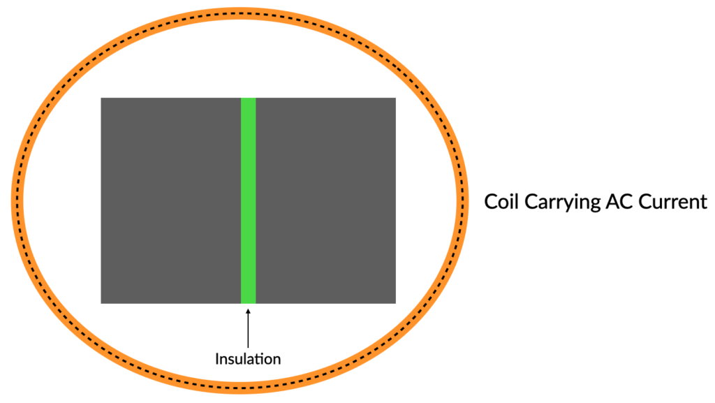
Now, the resistance has definitely increased. The induced voltage in each section is now half of what it was before.As a result, the eddy current will also decrease significantly. If the core is further subdivided, eddy current loss will gradually decrease. This is why the cores of transformers or AC motors and generators are always laminated.
There are a few ways to bypass a battery current sensor. One way is to use a resistor in place of the sensor. This will trick the system into thinking that there is no current draw and will allow the circuit to operate as normal. Another way is to use a transistor to switch the current around the sensor. This will allow the current to bypass the sensor completely and will not trigger the system.
First, you need to find the battery current sensor. It is usually located near the battery, either under the hood or in the trunk.
Then, you need to disconnect the negative terminal of the battery.
Next, you need to locate the two wires that go to the battery current sensor. One wire will be black, and the other will be white.
Then, you need to use a wire cutter to cut the black wire.
After that, you need to use a wire stripper to remove about ½ inch of the insulation from the end of the black wire.
Then, you need to twist the end of the black wire around the end of the white wire.
After that, you need to use a wire connector to connect the two wires together.
Finally, you need to reconnect the negative terminal of the battery.
1. The theoretical formula of three-phase transformer I and secondary current in power system is as follows: primary current = transformer apparent power (S) divided by square root of 3 divided by 0.9 divided by primary side voltage. Secondary current = transformer apparent power (S) divided by square root of 3 divided by 0.9 divided by secondary side voltage. 2, 10KV to 400V, 6KV to 400V three-phase distribution transformer primary current empirical formula is as follows: 10KV, the primary current is equal to the transformer apparent power (S) remaining to 0.066KV, the primary current is equal to the transformer apparent power (S) remaining to 0.13, the actual secondary current of the transformer is related to its secondary load, the calculation result of the secondary current mentioned in the above (1) is the value when the secondary load reaches the rated value, please note. Example: Calculation of primary and secondary current of 10KV/0.4KV, 630KVA three-phase transformer: 1. Theoretical principle I1=630KVA÷1.732÷0.9÷10KV≈40AI2=630KVA÷1.732÷0.9÷0.4KV≈1010A2; empirical formula I1=630KVA×0.06≈38A
Let Īa, Īb and Īc be the three line currents and Φa, Φb and Φc be corresponding components of magnetic flux in the core. Assuming that the CT is operating in the linear region (Read B-H Curve to get idea of linearity), magnetic flux because of individual phase current will be directly proportional to the phase current and hence we can write as below,
Φa = kIa
Φb = kIb
Φc = kIc
where k is constant of proportionality. Mind here that same constant of proportionality is used as all the three phase current are producing magnetic flux in the same core i.e. magnetic material.
Thus the resultant magnetic flux in the CBCT core,
Φr = k(Īa + Īb + Īc) …………………..(1)
But we know from theory of symmetrical components,
Īa + Īb + Īc = 3Ī0 = Īn
where, Io is zero sequence current and In is neutral current. Hence we can write as
Φr = kĪn …………………………(2)
Now let us consider two cases:
Case1: During normal condition
Īa + Īb + Īc = 0
Hence from equation (1),
Net resultant flux in the CBCT Core, Φr = 0 which means no secondary current and therefore the Earth Fault Relay won’t operate.
Case2: During earth fault, three phase current passing through the center of Core Balance Current Transformer will not be balanced rather a zero sequence current will flow. For example for single line ground fault,
If = 3Ia0 = In
Thus from equation (2),
Net magnetic flux in the CBCT core, Φr will have some finite value which in turn will induce current in the secondary circuit due to which earth fault relay will operate. Because of this reason, a Core Balance Current Transformer or CBCT is also called Zero Sequence Current Transformer.
A current sensor is an electrical device that measures the flow of electrical current along a specific electrical line. It accomplishes this by taking a precise measurement of the drop in voltage at a resistor placed in the path of the current. This allows the current sensor to generate an estimate of the level of current flowing through the line. The output of the current sensor is given either as a voltage reading or as a continuing current which is roughly proportional to the level of current moving along the tested path.
A current sensor works by attaching onto an active electrical line. Once attached to the line, the sensor reads the flow of electricity going through the line as it travels through a resistor. A resistor is a device placed in the path of a current which impedes the flow of electricity, ordinarily used to control and subdue the amount of current moving through a line. Voltage drops correspondingly as it passes across a resistor, depending on the overall level of resistance; by measuring the proportion of this decrease, the sensor can calculate the overall current of the line.
Traditionally used to protect circuits from damage and general current reporting, current sensors are now used in a much broader range of applications. These include performance monitoring and enhancement;protecting against overcurrents, which can overload a line and place it at risk;and battery operated circuits, such as those with battery rechargers. Rechargeable batteries can especially benefit from current sensing, because without an accurate measurement of current, they can easily become overloaded or otherwise useless.
After the physical connection between the battery and the charging pile is completed, the bms detects the adhesion of the relay in the charging/discharging circuit. When the detection passes, the charging circuit is switched on and the discharging circuit is disconnected.
When the battery enters the charging stage and the bms is reported without fault, the bms enters the current sensor fault detection mode;
The bms collects and stores a number of current detection values within a preset time t with a set step based on the current sensor arranged in the charging loop; At the same time, the bms obtains and stores a number of charging pile output current values corresponding to the current detection value one by one;
After reaching the preset time t, n groups of data are randomly extracted from several groups of data stored, and each group of data includes a current detection value and the corresponding output current value of the charging pile; Calculate the absolute value of the difference between two values in each set of data and write it as the detection value; Where n is a natural number greater than or equal to 2;
The detection value is compared with the preset threshold range; If n of the detection values are in the preset threshold range, after the end of charging, prompt the current sensor no fault and will be stored several groups of data clear; Otherwise, after the charging is complete, a message is displayed indicating that the current sensor is faulty and several groups of stored data are deleted
Electrical equipment that reduces the voltage from primary to secondary winding is called a step-down transformer. The role of a step-down transformer is the opposite of that of a step-up transformer.
The step-down transformer core is usually made of soft iron. Its structure is similar to that of a booster transformer – the ferromagnetic properties of the core help magnetization and energy transfer. Inductor coils are copper wires covered with insulators. The primary coil is connected to the voltage source, and the secondary coil is connected to the load resistor. The voltage provided as input to the primary coil creates a magnetic flux and induces EMF in the secondary coil. The load connected to the secondary coil requires a “step-down” AC voltage.
The voltage is proportional to the number of turns, the more turns the higher the voltage, the smaller the number of turns, the smaller the voltage. So in the process of depressurization, the number of turns in the input end will be more. The current is inversely proportional to the number of turns, the more turns, the smaller the current, the smaller the number of turns at the output end, the larger the current, the more turns at the input end, the smaller the current. So the current will increase after the depressurization.
We know that in a step-down transformer, the number of turns in the primary winding is greater than the number of turns in the secondary winding, Np>Ns. (Ns= number of turns in secondary coil, Np= number of turns in primary coil)
As we know, [Latex] \ frac {N_ {p}} {N_ {s}} = \ frac {V_ {p}} {V_ {s}} [/ Latex]
Therefore, Latex V_ = {s} \ frac {N_ {p}} {N_ {s}} \ times V_ {p} [/ Latex]
As the ratio [Latex]\frac{N_{s}}{N_{p}}<1\:,\: V_{s}
Just like the booster transformer, the power of the step-down transformer remains constant.As the voltage level drops, the current on the secondary coil increases to maintain balance.
COPYRIGHT © HEYI ELECTRICS SOLUTION