News | company news | Nov 05,2024
capacitor voltage transformer with a new insulation structure is described, indicating that the research and development of this product is successful.
Keywords: capacitor voltage transformer, ferromagnetic resonance , partial discharge, temperature rise
1 Introduction
The research topic of the capacitor voltage transformer with a new insulation structure is a technical research project of Guangxi Zhuang Autonomous Region. After research and trial production, the product has passed the technical appraisal of Guangxi Zhuang Autonomous Region.
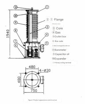
This capacitor voltage transformer adopts a new type of insulation structure, that is, the electromagnetic device is a dry structure.
It has the following technical and economic characteristics:
1.1 The electromagnetic unit is first insulated and then filled with slightly positive pressure SF6 gas for protection.
1.2 The anti-leakage effect is good, the annual gas leakage rate is less than 0.05%, and there is almost no need to replenish gas during the service life of the product.
1.3 The electromagnetic unit has no hidden dangers of oil leakage, and there is no need for annual inspections such as oil sample testing.
1.4 Since the electromagnetic device is inflated, the oil treatment process time can be saved, thereby shortening the production cycle of the product and improving the working conditions.
1.5 Provide technical support for the development of capacitor voltage transformers for GIS.
2 Main contents of the study
2.1 Product performance indicators
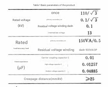
2.1.1 The main performance indicators of the product are shown in Table 1.
2.1.2 The tanδ of the product capacitor voltage divider is ≤0.10%, and the capacitance deviation does not exceed ±5% of the rated value.
2.1.3 The winding connection group of the intermediate voltage transformer is 1/1/1-12-12.
2.1.4 The annual gas leakage rate of the product should not exceed 0.5%.
2.1.5 The remaining performance of the product
shall comply with the corresponding

technical requirements of GB/T4703-2001 “Capacitor Voltage Transformer” and JJG314-1994 “Measurement Voltage Transformer” . HYPERLINK

2.2 Withstand voltage performance
Since the electromagnetic device is first insulated, it has passed the withstand voltage test even when the SF6 pressure is 0.1MPa, so the insulation strength can meet the requirements.
2.3 Ferromagnetic resonance
The performance of the capacitor voltage transformer depends on the quality of the ferromagnetic resonance performance, so a relatively detailed study was conducted. Since the insulation strength of the electromagnetic device can meet the technical requirements, the test study was conducted under the condition of SF6 pressure of 0.1~0.2MPa: When the damper parameters are reasonably matched, the ferromagnetic resonance test can be passed at a pressure of 0.1MPa; when the damper parameters are not reasonably matched, even if the resonance can be effectively suppressed, due to the high transient overvoltage, discharge will occur inside the electromagnetic unit at a pressure of 0.2MPa or even higher.
2.4 Partial discharge performance
Partial discharge performance is the focus of research on capacitor voltage transformers with new insulation structures. The performance of SF6 must reach above 0.3MPa before it can be compared with transformer oil. Therefore, the electromagnetic device must first be insulated and internal pressure equalization measures must be taken. When the SF6 gas pressure is 0.2MPa, the partial discharge of the electromagnetic device is 2~6pC; when the gas pressure drops to 0.12MPa, the partial discharge of the electromagnetic device is still 2~6pC; when the SF6 gas pressure is less than 0.12MPa, the partial discharge of the electromagnetic device is 10~50pC.
2.5 Temperature rise
GB/T4703-2001 “Capacitor Voltage Transformer” stipulates as follows:
a) When the secondary winding is connected to the rated load and the residual voltage winding is not connected to the load, apply 1.2 times the rated voltage for continuous testing until the temperature reaches stability. The temperature rise of each winding should not exceed 60℃.
b) After the temperature rise test of the electromagnetic unit under 1.2 times the rated voltage in item a) reaches a stable state, 1.5 times the rated voltage is immediately applied for 30 seconds, and the temperature rise of each winding should not exceed 70℃.
c) Under the above test conditions, the temperature rise of the core and other metal surfaces of the electromagnetic unit and the top layer of the oil should not exceed 70℃.
The heat dissipation of the electromagnetic device with new insulation structure is different from that in oil. Measures such as reducing the current density and increasing the heat dissipation surface are adopted to ensure that the temperature rise of the product does not exceed the value specified in the standard.
Under the three test conditions of a), b), and c), the temperature rise of each point does not exceed 12℃.
2.6 The gas leakage rate is
tested using HL-108 leak detector according to the method specified in GB11023-1989, and its annual leakage rate is 0.05%.
2.7 Accuracy

The accuracy test results are shown in Table 2.
3 Conclusion
3.1 The technical requirements of ferromagnetic resonance, partial discharge, temperature rise, accuracy, leakage rate, etc. of the capacitive voltage transformer with new insulation structure meet the requirements of the corresponding standards or technical conditions.
3.2 After the electromagnetic device is insulated, the partial discharge does not change significantly and is less than 10pC when the SF6 pressure is within the range of 0.12-0.2 MPa; the maximum partial discharge is 50pC when the SF6 pressure is less than 0.12MPa.
3.3 The insulation performance of the electromagnetic device can still meet the operation requirements when the SF6 pressure is 0.1MPa.
--- END ---

Feb 04, 2026
Why is single‑phase window type current transformer so popular in the South American electricity market? —Technical Analysis Based on the South American Power Bureau’s Bidding and Outdoor Environment In countries, like Brazil, Chile, Peru and Colombia the power infrastructure construction has kept growing in recent years. The distribution network upgrades, the energy grid integration and the… Continue reading Why single‑phase window type current transformer Dominate South America’s Power Grid

Feb 03, 2026
Why have single phase satuation current transformers (CTs) become an essential core component of switchgear in Southeast Asia? — Detailed technical analysis using the ICT series encapsulated transformer as an example. We examine the ICT series encapsulated transformer. In Asian countries such, as Malaysia, Indonesia, Thailand and Vietnam the low-voltage switchgear appears a lot in… Continue reading Why Single-Phase Saturation Isolation Current Transformers Are Essential in Switchgear

Jan 22, 2026
People use Current transmitter. Why do people use transmitters, in the chillers the air compressors, the generators and the IoT systems? In systems I see chillers, in commercial buildings air compressors in factories and generators, in data centers. The chillers, the air compressors and the generators all have one thing in common. In short devices… Continue reading Why Current Transmitter Matter in Chiller, Air Compressor, and Generator