News | company news | Nov 14,2024
Principle and Application of Photoelectric Current Transformer
High-voltage current transformer is a device that converts high-voltage signals in the power grid into low-voltage and low-current signals, thereby providing a unified and standardized current signal (traditionally analog, modernly digital) for the system’s metering, monitoring, relay protection, automatic devices, etc.; at the same time, it is an important equipment that meets electrical isolation and ensures personal and electrical safety.
High-voltage current transformer is a device that converts high-voltage signals in the power grid into low-voltage and low-current signals, thereby providing a unified and standardized current signal (traditionally analog, modernly digital) for the system’s metering, monitoring, relay protection, automatic devices, etc.; at the same time, it is an important equipment that meets electrical isolation and ensures personal and electrical safety.
High voltage current transformers can be divided into electromagnetic current transformers and electronic current transformers according to their principles. Electronic current transformers can be divided into active and passive magneto-optical glass types according to the working mode of the primary sensor.
1 Electromagnetic current transformer
An electromagnetic current transformer is a transformer that realizes current conversion through the principle of electromagnetic induction.
Since it has been widely used in power systems, only the main saturation problems are analyzed.
There are two common types of current transformer saturation: steady-state saturation and transient saturation. Steady-state saturation is mainly caused by the primary current value being too large, entering the current transformer saturation region, resulting in the secondary current being unable to correctly transform the primary current. Transient saturation is caused by the presence of a large number of non-periodic components, entering the current transformer saturation region.
1.1 Steady-state simulation analysis of current transformer

Current transformer model built in ATP

For more information on the excitation curves of nonlinear components, please visit: Power Transmission and Distribution Equipment Network
1.2 Current transformer transient simulation analysis

Transient saturation waveform with secondary load being a resistor (R=5)

Transient saturation waveform when the secondary load is inductor.
Keywords: photoelectric current transformer, principle, application
Abstract: High-voltage current transformer is a device that converts high-voltage signals in the power grid into low-voltage and low-current signals, thereby providing a unified and standardized current signal (traditionally analog, modernly digital) for the system’s metering, monitoring, relay protection, automatic devices, etc.; at the same time, it is an important device that meets electrical isolation and ensures personal and electrical safety.
High-voltage current transformer is a device that converts high-voltage signals in the power grid into low-voltage and low-current signals, thereby providing a unified and standardized current signal (traditionally analog, modernly digital) for the system’s metering, monitoring, relay protection, automatic devices, etc.; at the same time, it is an important equipment that meets electrical isolation and ensures personal and electrical safety.
High voltage current transformers can be divided into electromagnetic current transformers and electronic current transformers according to their principles. Electronic current transformers can be divided into active and passive magneto-optical glass types according to the working mode of the primary sensor.
1 Electromagnetic current transformer
An electromagnetic current transformer is a transformer that realizes current conversion through the principle of electromagnetic induction.
Since it has been widely used in power systems, only the main saturation problems are analyzed.
There are two common types of current transformer saturation: steady-state saturation and transient saturation. Steady-state saturation is mainly caused by the primary current value being too large, entering the current transformer saturation area, resulting in the secondary current being unable to correctly transform the primary current. Transient saturation is caused by the presence of a large number of non-periodic components, entering the current transformer saturation area.
1.1 Steady-state simulation analysis of current transformer
Current transformer model built in ATP
For more information on the excitation curves of nonlinear components, please visit: Power Transmission and Distribution Equipment Network
1.2 Current transformer transient simulation analysis
Transient saturation waveform with secondary load being a resistor (R=5)
Transient saturation waveform when the secondary load is inductor
From the system simulation software ATP, using its different excitation components to simulate the steady-state and transient waveforms of the current transformer, we know that before the core is not saturated, the primary current and the secondary current are completely proportional. When saturation is reached, the excitation no longer increases, and after saturation, no electromotive force is generated.
2 Electronic current transformer
2.1 Active electronic current transformer
The characteristic of active electronic current transformer is that the primary sensor is an air-core coil, and the high-voltage side electronic devices need to be powered by a power supply | voltage regulator to work. Its principle is shown in the figure below:

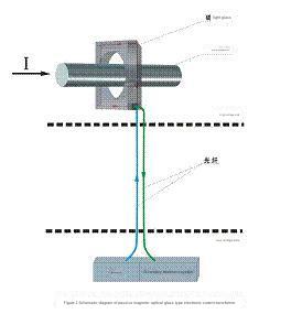
2.2 Passive magneto-optical glass type electronic current transformer The
passive magneto-optical glass type electronic current transformer is characterized by the primary sensor being magneto-optical glass and requiring no power supply. Its principle is shown in the figure below:
3 Working Principle
3.1 Faraday magneto-optical effect
Faraday magneto-optical effect: If the current passing through a wire is i, and the magnetic field strength generated around the wire is H, when a beam of linear deflected light passes through the magnetic field, the polarization angle of the linear deflected light will be polarized.
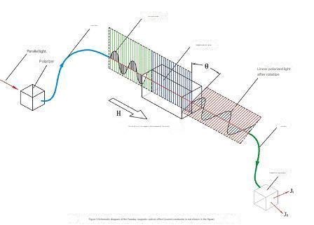
3.2 Application of Faraday magneto-optical effect in products
According to Ampere’s circuit law, in the circuit
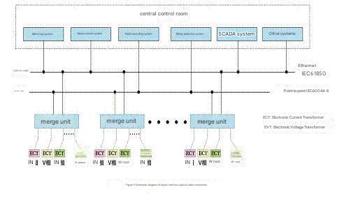
4 Secondary control system and interface connection form
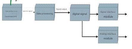
4.1 Secondary treatment system
4.2 Interface connection form
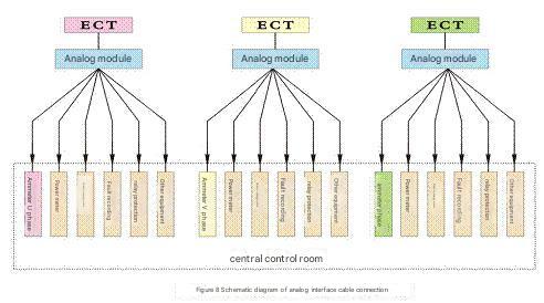
4.2.1 Analog interface connection form
4.2.2 Digital interface connection form
5 Features
⑴ No oil or air required, safe, reliable and maintenance-free.
⑵The sensor does not contain ferromagnetic materials, and there is no hysteresis, residual magnetism or magnetic saturation.
⑶ The primary and secondary sensing signals are connected by optical cables, which have excellent insulation performance and strong anti-electromagnetic interference ability.
⑷Small size, light weight, easy to install and use.
⑸ There is no danger of introducing high pressure due to open circuit on the low pressure side.
⑹It has optical and electrical digital interface functions, which facilitates the upgrading of the secondary part and the construction of digital substations.
--- END ---
COPYRIGHT © HEYI ELECTRICS SOLUTION


