News | company news | Apr 18,2025
How do switchgear designers choose the appropriate zero-sequence current transformer?
The switch cabinet is equipped with a zero-sequence current transformer (applicable to 0.38~66kV). Its characteristics are analyzed and how to choose a suitable zero-sequence current transformer is discussed in order to achieve the best use effect.
1 Overview
In medium voltage power system projects, our switchgear designers often encounter the problem of selecting zero-sequence current transformers in switchgear. Different zero-sequence current transformers have different characteristics and their application environments are also different. How to reasonably select zero-sequence current transformers in the design of switchgear has become a problem that switchgear designers often encounter. This article makes a preliminary discussion on this issue.
2 Characteristics and classification of zero-sequence current transformers
2.1 Zero-sequence current transformer and its characteristics
The zero-sequence current transformer is used to detect zero-sequence current, so it can be called a zero-sequence current filter. Its structure is similar to that of an ordinary through-type current transformer, except that its primary winding is the three-phase wires of the protected system (the three-phase wires pass through the transformer ring core together), and the secondary winding reflects the zero-sequence current of the primary system.
In a system where the neutral point is not directly grounded, the zero-sequence current transformer and the grounding relay constitute a single-phase grounding protection device. When the system is operating normally, the vector sum of the three-phase current on the primary side of the zero-sequence current transformer is zero, that is, Ia+Ib+Ic = 0. At this time, the zero-sequence current transformer is in a non-working state. When a single-phase grounding fault occurs (such as phase A), Ia+Ib+Ic=3Ioc, 3Ioc is equal to the vector sum of the capacitive currents of phases B and C to the ground, and zero-sequence magnetic flux appears in the iron core. This magnetic flux induces an electromotive force in the secondary winding, and the secondary current flows through the grounding relay to cause it to operate.
Simply put, the zero-sequence current transformer is used in conjunction with a relay protection device or a signal device when a zero-sequence grounding current is generated in the power system, so that the device components are activated to achieve protection or monitoring functions.
2.2 Classification of zero-sequence current transformers
According to different installation methods, it is divided into two types: integral type (such as LJ, LJZ) and retractable type (such as LXK). The appearance is shown in Figure 1.
According to the different product structures, there are two types: busbar type (such as LJM) and cable type (such as LJ, LJZ, LXK). The appearance is shown in Figure 1.
According to the different coordinated protection, it is divided into three categories: for small current grounding line selection device, for relay, and for microcomputer protection.

Figure 1 Zero-sequence current transformer
3 Selection of zero-sequence current transformer
3.1 Installation method
Considering the maintenance and installation, LJK and LXK type open-close zero-sequence current transformers should be used as much as possible. . LJ and LJZ types are old-style structures, and the cable heads must be remade during maintenance and replacement, so they are not recommended.
3.2 Product structure
It is selected according to the actual use. Generally, the cable type (such as LJ, LJZ, LXK) is used most of the time. The denominator type (such as LJM) is required in very few occasions, such as the zero-sequence protection of the generator outlet.
3.3 Cooperation and protection
Select according to the protective device used in conjunction. According to the different protective devices, they are divided into the following types:
1) Zero-sequence current transformer used in conjunction with a small current grounding line selection device
The small current grounding first-line device itself has no setting value. The zero-sequence current is only one of the criteria for the device. When the primary grounding current is small and the grounding is non-metallic, the zero-sequence current transformer must have a certain output to meet the threshold value for device startup, to select the grounding line or trip the corresponding line.
he load impedance of the device itself is not large, but each zero-sequence current transformer needs to be connected to the device through a cable, so the impedance of the cable is the main load impedance of the zero-sequence current transformer. The load impedance of this zero-sequence current transformer is generally about 2.5Ω.
This type of zero-sequence current transformer can generally be selected as a non-ratio type, with a primary zero-sequence current of 1 to 40A and a secondary current of about 0.02 to 1A.
2) Zero-sequence current transformer used with DD11/60 type grounding relay
The parallel impedance of the DD11/60 type grounding relay coil is 10Ω, and its action setting value is 0.03A. This type of zero-sequence current transformer can generally be selected as a non-ratio type, with a primary zero-sequence current of 2 to 4A and a secondary current of about 0.03 to 0.06A.
3) Zero-sequence current transformer used with DL11/0.2 current relay
The parallel impedance of the DL11/0.2 relay coil is 10Ω, and its action setting value is 0.1A. This type of zero-sequence current transformer can generally be selected as a non-ratio type, with a primary zero-sequence current of 10A and a secondary current of about 0.2A.
4) Zero-sequence current transformer used in conjunction with microcomputer protection device
The impedance of the microcomputer protection device is generally not more than 0.2 ~ 0.4Ω, and the setting value of the secondary action of the zero-sequence overcurrent protection is 0.1 ~ 20A. This kind of zero-sequence current transformer can generally be selected with the type with transformation ratio, capacity and accuracy requirements.
3.4 Selection of zero-sequence current transformer ratio
The application of zero-sequence current transformer generally uses a smaller ratio, such as: 50/5; 75/5; 100/5; 150/5; 200/5; 300/5; 20/1; 50/1; 100/1; 150/1; 200/1; 300/1, because the zero-sequence current transformer will only have an output when a ground fault occurs. People will not make the protection action only when the ground current is very large.
There is no need to consider avoiding load current) but because the primary winding is a power cable with only one turn, the secondary rated turns of the 50/5; 10/1 zero-sequence current transformer are only 10 turns. Therefore, the load characteristics of the 50/5 and 10/1 zero-sequence current transformers are poor. When the actual load impedance and the capacity of the zero-sequence current transformer are inconsistent, a large error will occur, and the error will also increase when the current is lower than the rated current. Therefore, try to use a larger ratio when permitted.
1) Selection of time-varying ratio for existing protection setting value
With the protection setting, the ratio is easy to select. For example, if the setting is that the protection is activated when the primary current is 80A, 100/5 or 100/1 can be selected, and the corresponding zero-sequence secondary current value is 4A or 0.8A, which is within the setting value of the zero-sequence overcurrent protection secondary action of 0.1~20A.
2) Selection of the transformation ratio of the resistance grounding system (small current grounding system, generally used for 66kV and below)
When the resistance grounding system is single-phase grounded, the current flowing through the fault point consists of two components, one is the capacitive current and the other is the neutral point resistance current, which are 90° out of phase. The zero-sequence current of the fault loop is equal to the vector difference between the grounding point current and the grounding capacitance current of this line, that is, equal to the negative value of the vector sum of the grounding capacitance current and the resistance current of all non-fault lines, see Table 1.
The recommended zero-sequence current transformer ratio is: 50/1; 100/1; 150/1; 200/1; 100/5; 200/5.

Table 1 Grounding current of resistance grounding system
a) Calculation of capacitive current of overhead lines
IC=(2.7~3.3)*U*L*10-3 (A)
Where: U — rated voltage of the power grid (kV)
L — Line length (km)
The coefficient 2.7 is applicable to lines without lightning arresters (wooden pole lines); 3.3 is applicable to lines with lightning arresters (wooden pole lines) and metal pole towers.
The increase in capacitive current caused by the power equipment in the substation can be estimated according to Table 2.

Table 2 Capacitor current increment caused by power equipment
b) The capacitive current of the cable is 25 times (three-core cable) to 50 times (single-core cable) larger than that of the overhead line of the same length. In the approximate calculation, IC=0.1U*L (A) can be used. The average value in Table 3 can also be used for calculation.

Table 3 Average value of cable line capacitance current (A/KM)
3) Selection of zero-sequence current transformer ratio for ungrounded neutral point and arc suppression coil grounding system (small current grounding system, generally used for 66kV and below).
When the neutral point is not grounded and the single phase is grounded, the current flowing through the fault point is only the capacitive current of the power grid to the ground. When the grounding current of this system is large, or the minimum starting current of the protection is small, a zero-sequence current transformer with a large transformation ratio can be selected, such as 50/1; 100/1; 100/5; 150/5 and above. However, some neutral point ungrounded systems generally do not allow the grounding current to exceed 10A, so the protection must be activated if it is below 10A.
When the arc suppression coil grounding system is single-phase grounded, due to the neutralization of the inductive current generated by the arc suppression coil and the capacitive current of the single-phase grounding, the grounding current generally will not exceed 10A (generally it is over-compensated, and the actual grounding current is already the inductive current).
Since integrated protection is used, a set value is required (when integrated protection is not used, a high-sensitivity zero-sequence current transformer and its matching relay are sometimes used, see 3.3 1~3)). The general set value is ≤10A. If the set value of the primary current is 5A, 100/5A or 20/1A can be considered. When the primary current is 5A, the secondary current is 0.25A, which generally exceeds the starting current of the integrated protection.
If the minimum starting current of comprehensive protection is greater than 0.25A, the transformation ratio of 75/5, 50/5, 15/1 or 10/1 must be selected. It is best to use an integral type zero-sequence current transformer for these transformation ratios, otherwise the accuracy will be worse.
4) Selection of transformation ratio for neutral point direct grounding system (large current grounding system, generally used for 110kV and above)
Single-phase grounding in a neutral point grounding system is a single-phase short circuit. The transformation ratio can be larger, such as 150/5: 150/1 or above. Do not make it too small, otherwise you will not be able to avoid unbalanced current. Be careful not to let the neutral line of the cable pass through the zero-sequence current transformer.
3.5 Selection of secondary rated current of zero-sequence current transformer
GB1208-2006 stipulates that the secondary rated current of current transformers are 1A and 5A. Considering that zero-sequence current transformers generally have a small transformation ratio, 1A is selected as much as possible (zero-sequence current transformers have more secondary rated turns) to improve load capacity. However, some comprehensive protection settings of 1A or 5A are selected by menu, and at this time, the secondary rated current of the zero-sequence current transformer must follow the secondary rated current value of the main current transformer.
3.6 Capacity Selection
The capacity must match the impedance of the protection device (including cable impedance) to ensure its accuracy.
1) Relationship between capacity and secondary impedance
Z=S/I2 or S=I2×Z
Where:
S: Capacity (rated load) is expressed in “VA”
I: Secondary rated current, (5A or 1A) represented by “A”
Z: The sum of the impedance of the secondary instrument or relay and the impedance of the secondary connection line, expressed in “Ω”
For example: ratio 100/5 capacity: 5VA
Z=S/I2=5/52=0.2 (Ω)
Transformation ratio 150/5 Capacity: 10VA
Z=S/I2=10/52=0.4 (Ω)
Transformation ratio 100/1 Capacity: 2.5VA
Z=S/I2=2.5/I2=2.5 (Ω)
Transformation ratio 50/1 Capacity: 1VA
Z=S/I2=1/12=1(Ω)
2) Relationship between accuracy and capacity (rated load)
GB1208-2006 stipulates: “Under rated frequency and rated load, the current error, phase difference and composite error shall not exceed the limits listed in Table 4.” Therefore, the capacity of the selected zero-sequence current transformer must match the impedance of the secondary circuit (device and circuit) to achieve the accuracy in the above table. If the selected capacity is larger than the actual capacity, the zero-sequence current transformer will have a positive error when used, otherwise a negative error will occur.

Table 4 Error limits of protective current transformers
3) Zero-sequence current transformer capacity supporting electronic protection such as integrated protection
If this type of protection is installed locally (on the switch cabinet), the loop impedance can be ignored, which is generally 0.2Ω-0.4Ω. The zero-sequence current transformer with a secondary rated current of 5A is 5VA, and the zero-sequence current transformer with a secondary rated current of 1A is 0.2VA-0.4VA. If the cable connection loop is long, the loop impedance should be considered and the capacity should be increased.
The capacity of the zero-sequence current transformer can be calculated based on the impedance (see Table 5) and the rated secondary current of the zero-sequence current transformer.
5) Secondary circuit cable resistance, see Table 6.

Table 6 Copper wire resistance table
3.7 Accuracy class and accuracy limit coefficient
The accuracy class is a grade given to current transformers. The error of the transformer under specified conditions of use should be within the specified limits. The accuracy class of the protection current transformer is nominally based on the percentage of the maximum composite error under the rated accuracy limit primary current, followed by the letter “P” (for protection). The standard accuracy classes of protection current transformers are 5P and 10P.
The accuracy limit factor is the ratio of the rated accuracy limit primary current to the rated primary current.
For example: ratio 100/5; 10p5
Where 10 is the composite error, p is the protection level, and 5 is the accuracy limit coefficient.
That is to say, when the primary current is 500A, the secondary current is about 25A, and the composite error is ≤10%. The accuracy limit coefficient is rarely used in zero-sequence current transformers. The zero-sequence current transformer should be operated at the rated primary current and rated secondary current as much as possible to obtain higher accuracy. Generally, the accuracy level of the zero-sequence current transformer is 10P.
3.8 Dynamic stability current and short-time thermal current
The dynamic stability current is the electric force generated when the primary current is very large, which will not cause mechanical damage to the current transformer. The primary winding of the cable-type zero-sequence current transformer is the power cable, and the transformer is not in direct contact with the power cable, so there is no requirement for dynamic stability current.
Short-time thermal current refers to the maximum primary current square root that the current transformer can withstand within one second without damage when the secondary winding is short-circuited (expressed as “kA-S”). It is generally above 5KA/1 second.
3.9 Primary and secondary current curves of zero-sequence current transformer

a.0~1, the initial stage, the primary current of the zero-sequence current transformer is small. Since part of it is used for excitation, the secondary current is also small. High-sensitivity zero-sequence current transformers generally work in this stage.
b.1~2, straight line part, the primary current is proportional to the secondary current, and the zero-sequence current transformer operates in the linear region. Zero-sequence current transformers with transformation ratio and accuracy requirements generally operate in this stage.
c.2~3, after point 2, the transformer enters the saturation zone. The larger the accuracy coefficient, the higher the point 2, and the later it enters the saturation zone.
3.10 Selection of inner diameter of zero-sequence current transformer
High-voltage power cables are generally cross-linked polyethylene insulated PVC sheathed power cables. When selecting the inner diameter of the zero-sequence current transformer, it is generally required that the inner diameter of the transformer must be 20~30mm larger than the outer diameter of the cable (see Table 7) to facilitate the installation and maintenance of the cable and transformer.
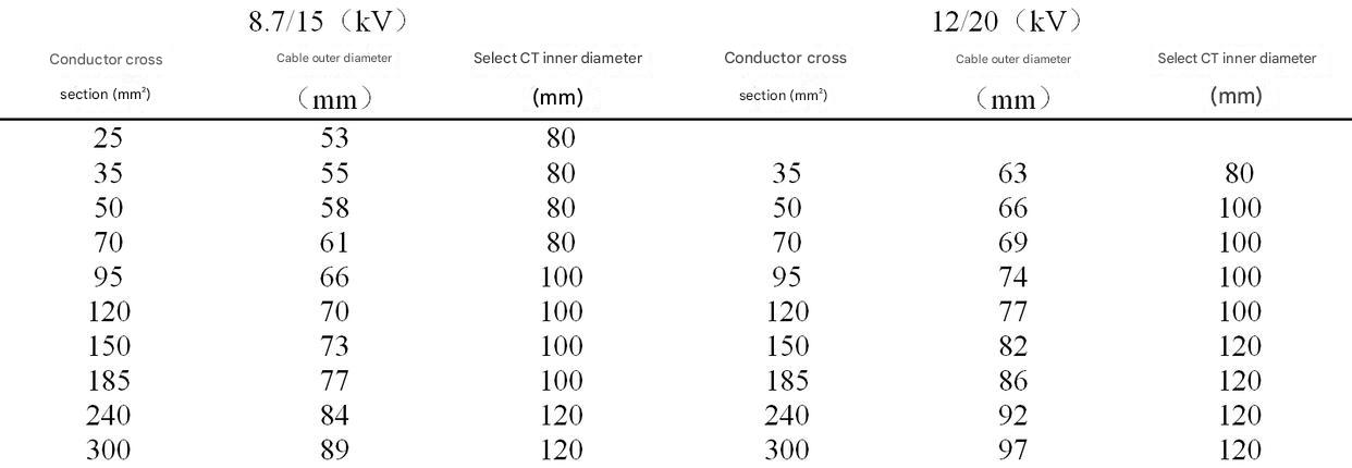
Table 7 List of transformer inner diameters
4 Conclusion
According to the above analysis method, the corresponding zero-sequence current transformer is selected through the product’s installation method, structural form, coordinated protection and other aspects combined with various operating modes of the power system (neutral point grounding, neutral point ungrounded, resistance grounding, arc suppression coil grounding) to achieve the best coordination between the zero-sequence current transformer and the corresponding protection device, thereby playing a role in protecting power equipment.
In the actual selection, we should try to choose resin casting type with beautiful appearance, compactness, easy installation and space saving. We should carefully weigh the cost performance of different zero-sequence current transformers to further reduce the design cost of the switch cabinet and increase the market competitiveness of the switch cabinet.
--- END ---
COPYRIGHT © HEYI ELECTRICS SOLUTION


