News | company news | May 20,2025
How charging pile construction promotes carbon neutrality in Europe?
European Electric Vehicle Charging Station Market
Increasing technological advancements in charging stations, including smart charging, and the integration of ultra-fast charging stations capable of providing 350 kW charging speeds are strengthening the industrial landscape. The continued and exponential adoption of AI-driven smart charging services, including V2G technology or bidirectional charging and energy management systems, is improving the efficiency of EV charging stations, which in turn will form a positive offline market growth outlook.
Increasing integration of renewable energy sources into the electricity supply, and growing concerns about sustainability, are leading to the use of solar and wind energy to meet stable, eco-friendly energy needs. For reference, the governments of the Netherlands and Germany will launch solar charging hubs in 2025 as part of their sustainable mobility initiatives. These developments, including unconventional forms of energy to power the stations, will lead to the region’s commitment to a strong and futuristic network of charging stations.
Learn about EV charging technologies for BEVs and electric trucks
Charging options for passenger battery electric vehicles (BEVs)
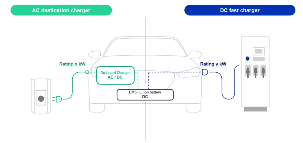
For passenger battery electric vehicles (BEVs), charging can be done using either an AC wallbox (using the car’s onboard charger (OBC)) or an off-board DC charger with a maximum charging power typically in the 100-250 kW range.
The choice of AC/DC charging point and power level for an EV depends on the charging time and the required charging range.
In passenger BEV applications, AC charging points account for the majority and are typically deployed in homes and buildings, while DC charging points are deployed at destination charging and en route charging, as time is an important limiting factor.
AC vs. DC Charging: Speed, Cost, and Availability
Access to easy and widespread electric vehicle supply equipment is a cornerstone of the transition to electrification in the transportation sector.
There are two options for charging a battery electric vehicle (BEV): utilizing the BEV’s onboard charger (OBC) or connecting an external AC/DC converter directly to the BEV’s battery.
The choice between AC or DC charging depends on factors such as the available charging time and the cost of the charging technology.
AC charging is often referred to as low-speed charging, using cost-effective hardware. In contrast, DC charging enables fast charging because the power of the car’s OBC is no longer a limitation, requiring more expensive equipment (offboard DC fast charger).
DC fast charging is essential for on-the-go charging, meeting the charging needs of about 30 minutes at a state of charge (SOC) of 20-80%. It plays a vital role in eliminating range anxiety and promoting the popularization of charging points in public places.
On the other hand, AC charging accounts for the majority of chargers in residential areas, providing a large number of charging options.
How to ensure electrical safety when charging electric vehicles using residual current monitors ?
Frequent charging of high-voltage batteries in electric vehicles (EVs) places high demands on the mechanical stress of charging cables and connectors. If the insulation is damaged, live metal parts are exposed, or if a shunt occurs in the on-board electronics, life-threatening residual currents can flow through the body of the EV user. What is particularly troublesome is that AC-sensitive type A residual current devices (RCDs) cannot detect all forms of DC residual current.
To prevent electric shock accidents, electric vehicle power equipment (EVSE) manufacturers must use RCDs in power electronics that can trip within milliseconds when AC and DC residual currents of several mA occur.
This article explains what residual current looks like, how to measure it, and where to install an RCD in a charging circuit. It then introduces residual current monitors (RCMs) from Littelfuse , which system designers can use to add DC shock protection to their EVSE equipment in a cost-effective and time-saving way. It also explains which EV charging modes these current sensors are suitable for and how to use them.
Residual current in electric vehicle charging circuits
Charging electric vehicles at AC voltages up to 400 V and DC voltages up to 1000 V requires electric vehicle users to take careful protective measures when operating charging equipment. Due to the harmonic-rich asymmetrical switching pulses generated by charging stations and on-board chargers, as well as DC link voltages of several hundred volts, various types of AC and DC residual currents may be generated through shunting, coupling effects, insulation faults, and leakage faults.
Power electronic circuits such as rectifiers, switching converters, frequency converters, as well as inverters and phase angle control systems have a variety of load current characteristics. The residual current that may be generated is divided into sinusoidal AC, pulsed DC and straight DC. These forms of residual current are dangerous to humans.
A good understanding of the residual current waveform can help EV repair shops and electricians monitor residual current in EV circuit board electronics, EVSE, or charging stations.
Tripping characteristics of various RCD types
Generally, personal protection against electric shock in electrical equipment is governed by the IEC 60479 and UL 943 standards. The important AC and DC residual current ranges specified in these two standards are 6, 30, 100, 300, 500 and 1000 mA, respectively, with trip times of 20 to 500 ms. Common trip thresholds in electric vehicle charging circuits are 6 mA DC and 30 mA AC.
Now, system designers can easily implement specific personal protection requirements in charging circuits by simply selecting the appropriate standard RCD type.
Installing RCDs in electric vehicle charging circuits
A type or F type RCD can only detect AC residual current and DC pulsating current, which is not enough to protect the electric vehicle charging circuit. We must also consider the various DC residual currents that may appear in the on-board charger or battery management system.
Therefore, IEC 62196 defines two options for residual current protection: using a fully current-sensitive type B RCD (or type B+), or using a type A RCD in combination with a residual DC monitoring system with IΔn DC ≥ 6 mA in accordance with IEC 62955. The DC fault current monitoring device can be installed either in the wall box, in the building electrical system, or in both locations.
Since AC-sensitive Type A or Type F RCDs are often present in the building electrical system, designers can take a more cost-effective approach by adding 6 mA DC residual current monitoring devices in the Mode 3 wallbox or charging station, and in the cable control box (ICCB) of the Mode 2 charging cable (Figure 1, Cases 2 and 3).
In the future, Europe needs to continue to increase investment in charging pile construction, solve the problem of uneven distribution, speed up deployment, and continuously innovate charging technology to improve charging efficiency.
Electric vehicle charging mode
Electric vehicle batteries can be charged in different charging modes, depending on the available on-site power connection, connection plug, charging cable, and charging technology used in the vehicle and charging station. In Europe, electrical energy can be input to the car via single-phase AC (230 V/3.6 kW), three-phase AC (400 V/22 kW), or high-voltage DC charging stations (up to 1000 VDC/500 kW). Figure 2 shows the four charging modes defined in the IEC 61851 standard.
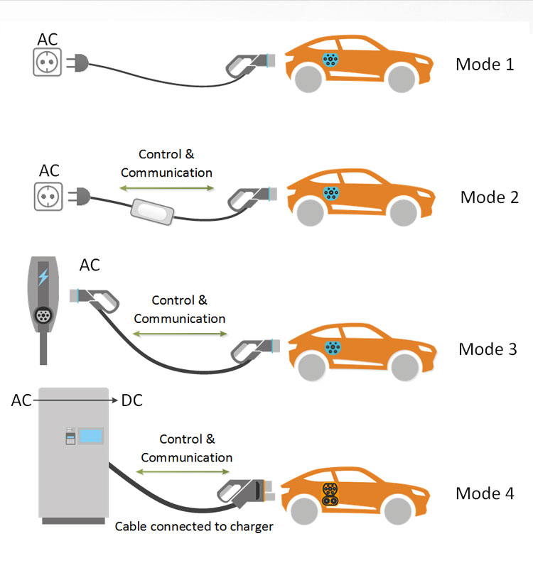
Figure 2: Schematic diagram of the four charging modes defined in the IEC 61851 standard. (Image source: bestchargers.eu)
Mode 1 (single-phase AC charging, up to 3.6 kW; default charging mode)
In this case, the electric or hybrid vehicle is connected to a standard 230 V household socket via a simple passive cable and charged at low power with a maximum power of 3.6 kW via an on-board charger. This charging scheme does not provide adequate DC residual current protection for the user. Typically, only AC-sensitive type A RCDs are installed in the building’s electrical system.
Mode 2 (single-phase/three-phase AC charging via ICCB charging cable, up to 22 kW)
When charging electric vehicles using household sockets and three-phase sockets, the Mode 2 Charging Cable with Type 2 Vehicle Plug contains an In-Cable Control Box (ICCB) that performs safety and communication functions to prevent overloading the socket.
The ICCB must integrate the following protection functions:
Determine polarity and monitor the protective conductor (PC); only a few ohms of loop impedance are permitted between the neutral conductor and the PC.
Test the electrical connection between the PC and the metal chassis.
AC and DC residual current circuit breakers protect against current accidents.
Monitors/shuts down the charging process in the event of abnormal conditions, such as current fluctuations due to corrosion of the plug contacts or cable breaks.
Monitors the temperature inside the ICCB and both plugs and shuts down when necessary.
Charging Power Control: A pull-down resistor on the control pilot line (CP) signals the cable current load rating to the wallbox and the electric vehicle; a pulse width modulation (PWM) signal on the charging control line (CC) signals the wallbox charging power capability to the electric vehicle.
Mode 3 (single-phase/three-phase AC charging via wall box, up to 22 kW)
For EV charging, the passive Mode 3 cable can be connected to a wall box in a private home or to a public AC charging station in a parking garage. Both integrate the same protection features as the ICCB mentioned above.
Mode 4 (direct battery DC fast charging, up to 500 kW)
The DC/HPC station for electric vehicles provides higher charging currents compared to Mode 2 and Mode 3. The Supercharger incorporates a shock protection device to prevent electric shocks due to AC and DC residual currents; different charging cables can always be securely connected.
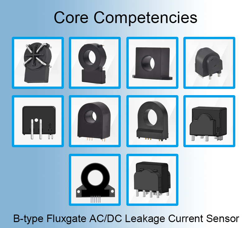
HYCA series products of Heyi Electric for charging pile construction
The HYCA-01 from Wenzhou Heyi Electrical Co., Ltd. is a precision residual current detection module designed for safety-critical applications. This compact PCB-mounted solution offers comprehensive AC/DC leakage current monitoring with advanced self-test capabilities, making it particularly suitable for electric vehicle charging infrastructure and industrial power systems.
HYCA Series What is the difference?
Where is the HYCA series recommended for use?
Technical features of the HYCA series:
Current Ratings
Output Signals
Environmental & Reliability
Safety & Insulation
Timing Characteristics
Self-Test & Calibration
Mechanical & Installation
Compliance & Standards
--- END ---
COPYRIGHT © HEYI ELECTRICS SOLUTION


