News | company news | Oct 11,2024
Overview
Metering type low voltage current transformer is a current transformer that provides current to electric energy meters and other similar electrical appliances. It is widely used in the measurement of current in low voltage distribution systems. The main accuracy levels (given for current transformers) are: 0.2, 0.5S, 0.2S, etc.
This article introduces a metering current transformer independently developed by China. The shell is made of imported polycarbonate injection molding that is flame-retardant and temperature-resistant to 140°C. The iron core is made of ultra-microcrystalline and the secondary conductor is made of high-strength electromagnetic enameled wire. The product has a novel structure, beautiful appearance, easy installation, small size, light weight, high accuracy and large capacity. The product complies with the national standard GB1208-2006.
Working Principle
The working principle of the low-voltage current transformer is shown in Figure 1. The primary winding of the current transformer is connected in series in the measured circuit. I1 is the line current, that is, the primary current of the current transformer, N1 is the primary turns of the current transformer, I2 is the secondary current of the current transformer (usually 5A, 1A), N2 is the secondary turns of the current transformer, and Z2e is the impedance of the secondary circuit equipment and connecting wires. When the primary current flows in from the P1 end of the current transformer and out from the P2 end, when the secondary Z2e is connected, according to the principle of electromagnetic induction, the current transformer secondary winding has a current I2 flowing from S1, through Z2e to S2, forming a closed loop. It can be obtained that the current is I1×N1=I2×N2 in an ideal state, so I1/I2=N1/N2=K, and K is the transformation ratio of the current transformer.
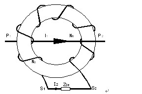
Figure 1 Working principle of low voltage current transformer
Technical indicators
Primary current measurement range 5-2000A, secondary current 5A, 1A; rated working voltage AC0.66kV (equivalent to AC0.69kV, GB156-2003); rated frequency 50-60Hz; ambient temperature -30℃~70℃, maximum temperature resistance 120℃; altitude ≤3000m; power frequency withstand voltage 3000V/1min 50Hz; used in places without direct invasion of rain and snow, serious pollution and severe vibration.
Problems and application examples in low voltage distribution systems
In low-voltage power distribution systems, users often encounter the problem of distinguishing between accuracy levels 0.2 and 0.2S for current transformers used for measurement, as well as the impact of incorrect wiring (reverse polarity) on measurement.
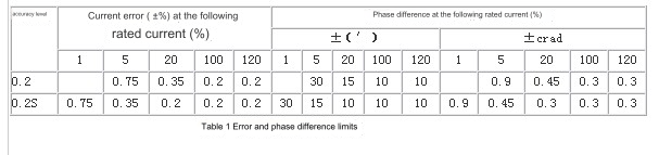
1 The difference between accuracy level 0.2 and 0.2S is shown in Table 1
2 Effect of incorrect wiring (reverse polarity) on measurement
(1) Metering connection method: three-phase three-wire
The active power when the wiring is correct is: P = Pa + Pc = UabIa.cos (30° + φa) + Ucb.Ic.cos (30° – φc); when the three-phase circuit is balanced, Uab = Ucb = √3U, Ia = Ic = √3I, that is, P = 3UI cosφ; if the polarity of the current transformer of phase A is reversed, see the wiring diagram (a) and the phasor diagram (b) for details.
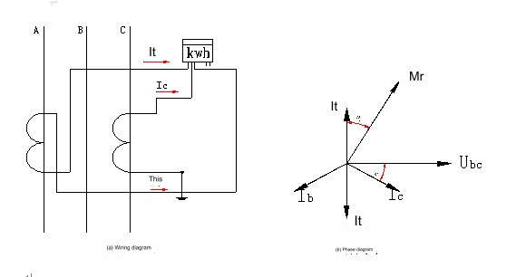
Thus we can conclude that the common line current Io is √3 times the phase current;
The angle of the current lagging the voltage of the energy meter 1 is: 30°+φa+180°=210°+φa;
The angle of the current lag voltage of the energy meter 2 is: 30°-φc;
Therefore, the active power when the wiring is wrong is:
P´=Pa´+ Pc´=Uab.Ia.cos(210°+φa)+ Ucb.Ic.cos(30°-φc)=UIsinφ;
If the power factor cosφ=0.9, when the polarity of the A-phase metering transformer is reversed, the leakage electric energy is the actual metering electric energy:
P/ P´-1=3UIcosφ/UI sinφ-1=3×0.9/0.4359-1=5.19 times;
(2) Metering connection method: three-phase four-wire
The active power when the wiring is correct is: P = Pa + Pb + Pc = UaIa.cosφa + Ub.Ib.cosφb + Uc.Ic.cosφc; when the three-phase circuit is balanced, Ua = Ub = Uc = U, Ia = Ib = Ic = I, that is, P = 3UIcosφ
If the polarity of the current transformer of phase A is reversed, see the wiring diagram (c) and phasor diagram (d) for details.
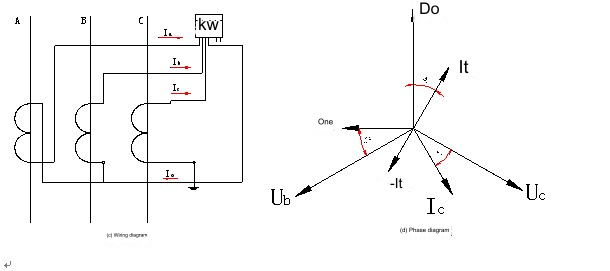
Thus we can conclude that the common line current Io is twice the phase current, and the A phase current is -Ia;
Therefore, the active power when the wiring is wrong is:
P´=Pa+Pb+Pc=-UaIa.cosφa+Ub.Ib.cosφb+ Uc.Ic.cosφc= UIcosφ;
When the polarity of the A-phase metering transformer is reversed, the leakage electric energy is the actual metering electric energy:
P/ P´-1=3UIcosφ/UIcosφ-1=2 times;
3 Precautions during use
(a) When connecting the current transformer, the same-named terminals must be kept consistent, i.e. P1, S1; P2, S2.
(b) During normal operation of the current transformer, the secondary circuit must not be open to prevent the secondary open circuit from generating high voltage and affecting personal and equipment safety.
Quotation plan

Conclusion
The product has been applied in power metering of power distribution monitoring system in many industrial and mining enterprises, which effectively reduces the investment cost and produces better social and economic benefits
--- END ---
COPYRIGHT © HEYI ELECTRICS SOLUTION


