News | company news | Nov 08,2024
If you need to measure current from an AC source, a current transformer can be a low-cost, accurate option. You can find current transformers designed for 50/60Hz power line applications and higher frequencies that are more suitable for industrial/scientific machinery or process monitoring. Current transformers are non-contact and non-intrusive, which means that with many models, you don’t need to run the AC source through the board. Instead, the wires are passed through the openings of the transformer, or the transformer itself may open to allow it to catch on the wires.
The wires running through the current transformer act as both a single winding of the transformer and the primary coil. The body of the transformer has tens to thousands of windings that form the secondary coil. Unlike voltage transformers, current transformers have an inverse ratio. This means that a current transformer with a ratio of 1000:1 will produce 0.001A of current in the secondary coil for every 1A of current in the primary coil.
You’ll find current transformers with winding ratios suitable for measurements from single amps up to thousands of amps, which makes them suitable for a wider range of applications than PCB mounted/conductive current sensors.
In this project we are going to look at a few ways to convert the output of a current transformer into something more useful for interfacing with a microcontroller. At first glance this may seem like a very simple task, but as you dig deeper current transformers become more interesting, especially if you have never used them before. As such this project is going to be a bit more practical and hands on than some of my previous projects. First we are going to pull out our breadboard, function generator, and oscilloscope to learn about current transformers. Then we are actually going to build a precision rectifier board to be able to best utilize the current transformer with a microcontroller ADC input.
Basic Output of a Current Transformer
Using Ohm’s Law (V=IR) we can convert the current output of the transformer into a usable voltage. I am using the Talema AC1010 as the current transformer for everything in this article. For this sensor a 100 ohm load resistor will produce a 1V RMS voltage at 10A on the wire running through the current transformer
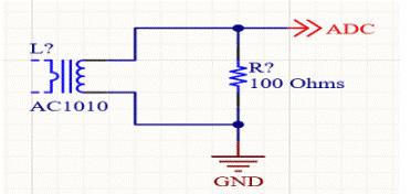
With the transformer and resistor connected in parallel, you can simply connect one end of the structure to ground and the other end to an ADC to get a reading. However, this is probably a very bad idea. I only present this schematic to show the simplest way you can see a current transformer in action.

This is what the ADC output looks like on the oscilloscope. This is the output of my function generator, used to simulate a 7amp load, not the actual current sensor output – we’ll get to that shortly.
There are some important things to note here:
the signal is 2 volts peak to peak, but I’m talking about a 7 amp (that’s 0.7V) load!
The waveform is AC, so it’s +1V to -1V, which a microcontroller isn’t going to like.
The current transformer is just converting the current on the line, so your actual current will be the root mean square (RMS) of the waveform. The function generator outputs an almost perfect sine wave, but depending on your load, the current in an actual current transformer circuit may not be so perfect. A rough estimate of the current can be determined by just reading the peak voltage, but to get an accurate current measurement you will need to take several measurements to determine the total area under the curve (that’s the current draw).
The 2V peak to peak output is centered around ground, which isn’t very microcontroller friendly. We need to do something with the signal to make it more useful.
Biasing the Ground
Since the current transformer is just a floating voltage across the load resistor, the only way we can reference the transformer voltage is to ground it. Instead of grounding it, we can tie one leg to a DC bias voltage obtained via a resistor divider. This will provide a DC offset to the AC waveform.
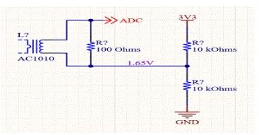
This is a simple voltage divider and will have half of the 3.3V input at the midpoint between the resistors, producing a DC offset of 1.65V. Now, our 2V peak-to-peak waveform should swing around 1.65V over a range of 0.65V to 2.65V.

We can show this with an oscilloscope. I’m using some really cheap bulk resistors that won’t give me 1.65V in the center of the voltage divider. The blue is the 2V peak-to-peak signal, and the yellow is the signal with the DC offset.

I have a 1.1kW heater pad for an upcoming project and if I run it through an AC1010 current transformer and the same resistor I get an offset voltage sine wave. Notice how the waveform is not as perfect as the function generator waveform. Real loads are almost never perfect sine waves.
ADC Resolution
The downside to this method of measurement is that we have offset the voltage of the waveform to keep it within the range of the ADC, which means we can’t effectively use a lot of the voltage range. A
relatively low cost modern ARM Cortex microcontroller will have a 12-bit ADC, while some newer ADCs come standard with 14-bit or 16-bit ADCs and some older ADCs have 10-bit ADCs. For the purposes of this article though, I will be working under the assumption of a 12-bit ADC.
A simple 12-bit ADC will give us 212 or 4096 possible values. Applied to a 3300mV range this gives us a resolution of about 0.8mV. The total peak-to-peak voltage span for the load shown above is 1219mV, which should be a load of around 4.5-4.7A. 1219mV gives us 1523 possible values (displayed at our calculated resolution), which translates to about 3mA per ADC value when using our 100 ohm load resistor (remember: this is RMS!). This is more than enough for this 10 amp sensor. However, this may not be enough for you as you start reading larger and larger amperages or using a current transformer with more turns than an AC1010. Still,
this offset DC voltage is the simplest way to read a current transformer, requiring only 3 resistors total. You should also include TVS diodes to clamp the load to ensure that it doesn’t exceed the maximum voltage rating of your microcontroller during current spikes.
Precision Rectifier
You can use a bridge rectifier to rectify the waveform from a current transformer, but the forward voltage of the diode will greatly reduce the current sensing capability. The diode can easily eliminate more than half of the current sensing range, making anything below half of the sensor’s ampere range unreadable. Worse, the forward voltage of the diode will vary depending on voltage, temperature, and other conditions, so the rectified voltage is unlikely to be particularly useful.
Instead of a simple bridge rectifier, we can build a precision rectifier using two op amps. One op amp will give you a half-wave rectifier, which may be sufficient for some amperage measurements. The extra component cost of a full-wave rectifier is negligible though, so we can use that even in cases where a half-wave rectifier would suffice. Precision rectifiers are common in instrumentation applications such as this, and are an excellent way to produce a usable voltage. Also, since an op amp is used, the rectified waveform can be amplified when used as well.

I am using an inexpensive AD8542 op amp, which has two amplifiers in one package. While op amp trims are surprisingly accurate these days, it is important to note that having two amplifiers in the same package greatly increases the likelihood that both amplifiers will apply the same gain. In my final design, I will also use 0.1% resistors for the same reason. Finally
, I have a simple 600Hz RC filter on the output of the op amp to remove any AC noise that may have been picked up. The cutoff frequency of this filter is high enough that it will not affect the 50Hz signal.
However, the prototype on my breadboard used mystery resistors that claimed to be 5%, so our results are not very accurate.

Notice that the negative wave is slightly lower voltage than the positive wave. That’s because the resistors I used weren’t particularly well matched.

This error is not noticeable when we test with the heating element as the load. As before, the blue is the waveform from the current transformer and the yellow is the output of the precision rectifier.
When I give the op amp a ground reference (rather than a negative voltage), we have a small DC offset of 103mV for the rectified signal. This offset is acceptable for my application because it is consistent so it can be programmed into the microcontroller during board testing.
ADC Resolution
For the same load applied with the voltage compensation method, we get a 1219mv signal. However, with the precision rectifier and a 2x output gain, we actually read 2066mV peak-to-peak for this signal. We just doubled our resolution!
Since we are also able to view the raw waveform on the oscilloscope this time, we can calculate the RMS voltage of this waveform to determine the current draw. 442.9mV should indicate that we are pulling 4.429A through the heater. If correct, our 12-bit ADC has a current sensing resolution of 1.71mA, which is more than enough for my application.
Is the current sensor correct?
The question is, how can I verify that the current measurement is correct, or at least close? Every device has its own tolerance and precision, and the AC1010 datasheet’s logarithmic graph makes it difficult to read the tolerance of this device using a 100 ohm load resistor. Instead, we can calculate the expected load and compare it to the waveform measured by the sensor. Ideally, I would do this with multiple loads, but for this article, I will only use it to see if we are even close to the expected results.
Measuring the Heating Element
I measured the heating element using a 4-wire resistance measurement. After letting my multimeter average the reading for a while, it stabilized at 50.262 ohms.

Measuring load resistance
Considering how bad some of the 10k resistors I was using were, I was pleasantly surprised to find that the 100 ohm load resistor I had been using was 99.983 ohms.

Measuring AC Power
After being surprised that the load resistor was so close to nominal, I didn’t expect the same result with my AC voltage. Other countries I’ve lived in claim the voltage is 240V, but I measured 270VAC at the wall. The UK is 240V +10/-20%, and my house is 239.632V! To me, this is amazing.
Putting it all together
Now going back to Ohm’s Law, V = IR, 239.623V into a 50.262 ohm load, means we should see 4.76766A. In the last test using the precision rectifier we measured 4.429V RMS from the sensor. With a 99.983 ohm load resistor this should equal 4.4297A, which means we are discounting about 7%.
You can buy more precision current transformers, but these are cheap and the 10% tolerance is more than enough for my application.
Precision Rectifier Design
The design of a precision rectifier is fairly simple and very common in precision instrumentation applications. The first op amp inverts the signal and the ground reference cuts off the negative voltage, giving us only a positive half rectified signal. To ensure symmetry of the rectified waveform the first op amp gain is unity (R3 = R6). The second op amp combines the two signals and with resistors R8 and R5 set to 5k and 10k we double the output voltage.

Maximum Voltage Considerations The
maximum voltage the op amp is capable of outputting is V+ minus the diode forward voltage. This should be kept in mind during the precision rectifier design. If the gain is too high to use the full voltage range that the ADC can read, the top of the waveform will be clipped.
Maximum Current Considerations
You should also leave some room for amperage peaks. The actual current load that this sensor will read should be less than the 1100W load I applied for testing. However, even at full scale, this precision rectifier will have an output of about 2.8V at the full 10A load. This should be more than enough for my application, but keep this in mind in case it is not suitable for your application.
Let’s design a PCB!
The board design for this project is very simple as it has only a few components and no high frequencies. This would make a very good first PCB project for a new Altium user.
I plan to use 6 of these current transformers in an upcoming project, so I wanted to keep the design as small as possible. I added Molex SL 70553 series latching connectors to the board, which would make this a practical standalone board for measuring current inside machinery or other equipment. With the width determined by the current transformers and the length of the board determined by the connectors, we end up with a 25x25mm area in which to lay out the circuit. I am using 0603 components to make this project “beginner friendly” for assembly and hand soldering. The MSOP-8 version of the AD8542 op amp might work against this, but it also comes in a SOIC-8 package and can be easily mounted on an extra board. Modifying the design to use a larger IC might be a good exercise for a beginner.
I also added some large 1206 decoupling capacitors to the design. If this board is at the end of a cable, then the on-board capacitance will always be fine.
This design is either 50hz or 60hz depending on what country you live in, so there are no signals that require impedance matching or any other considerations that complicate the board design process.
--- END ---
COPYRIGHT © HEYI ELECTRICS SOLUTION


