News | company news | Sep 18,2024
Key considerations in designing a car charger
After switching to electric vehicles (EVs), the biggest change drivers may feel is the way they recharge differently. Specifically, they no longer need to drive to a gas station, but must find an available charging point.
Although the number of public charging points is increasing rapidly, many people still prefer to charge at home. Many high-power public charging stations provide direct current and are able to charge the battery directly, but home charging stations are AC, so it is necessary to use an on-board charger (OBC) to convert it to direct current to charge the car.
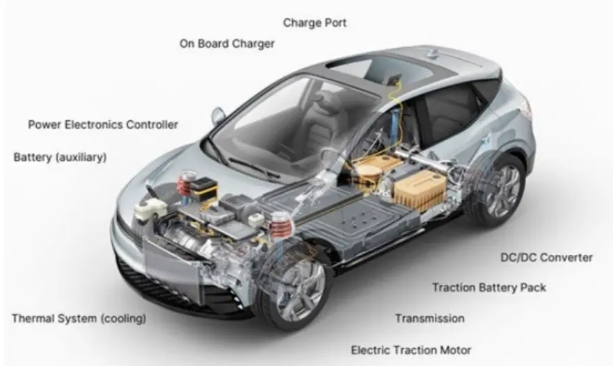 Figure 1: Typical electric vehicle drivetrain analysis
Electric vehicle technology is advancing rapidly, and automakers are migrating from 400 V to 800 V battery architectures. At the same time, consumer demand continues to grow, battery capacity (kWh) continues to increase, such factors make OBC must also continue to improve. In addition, many people want to improve the charging speed of electric vehicles, so the power of the OBC has been increased from the earlier design of 3.6 kW to 7.2 kW or 11 kW without exceeding the grid power supply capacity.
 Figure 2: Classification of pure electric vehicle (BEV) charging piles
Key design considerations for OBC
Before embarking on a full-scale OBC design, designers must understand the key design parameters that will affect the choice of devices and topologies.
Power levels directly affect the user experience, so determining power levels is a crucial first step. Simply put, the higher the power of the OBC, the shorter the time it takes to charge the battery. In many cases, users will charge their cars at home, when they are usually busy with other things or resting, so charging time is not much of an issue. However, for the charging needs of the middle of the trip, the charging time is very critical. The rated power of the level 2 charging pile is generally about 7.2 kW or 11 kW. OBC power levels should be designed to match grid capacity and circuit breaker limitations, such as maximum current. Take 230V power grid as an example. In a single-phase design, a 7.2kW level 2 charging pile will consume up to 32A of current. The 11 kW 2-stage charging pile is optimized for three-phase AC inputs, consuming up to 16A per phase.
Electric vehicles are accelerating adoption in the global market, but grid voltage differences in different countries pose challenges for vehicle charging. 110V AC is widely used in North America, while 230V AC is more common in Europe and China. The power industry typically uses a “universal input” design of the 86-264V AC, which allows the same OBC to be used no matter where the vehicle is shipped.
Through the same charging port, electric vehicles can be charged by means of a quick charging pile that provides direct current on the roadside, and AC-DC conversion is not required inside the OBC, so a bypass function is usually designed so that direct current can flow directly into the high-voltage battery.
Energy efficiency is a key parameter of OBC. The higher the efficiency, the more power can be delivered to the battery at a given time, which in turn can reduce the charging time, which is particularly effective when the power per phase of the grid is close to the limit.
The less energy efficient the OBC, the more heat is generated inside the device. Not only is this wasteful, but it also requires additional heat dissipation measures, which is challenging given the limited space available in modern electric vehicles. The increase in the size and weight of the OBC will increase the weight of the vehicle and increase the amount of electricity consumed during driving, ultimately leading to a shorter overall vehicle range.
Improving energy efficiency is a top priority for power designers, and it is a complex challenge that requires a multi-faceted approach. Although the conversion topology and control scheme also have a large impact, the choice of devices (especially MOSFETs) can also play a significant role in achieving better energy efficiency.
Power level in OBC design
Typically, an OBC consists of three main modules: an EMI filter, a power factor correction (PFC) stage, and an isolated DC-DC converter containing separate primary and secondary sections.

Figure 3: Block diagram of the main power stages in a typical OBC (Source: ON)
The PFC level sits at the front end of the OBC and is responsible for performing many important functions. First, it recites the input AC grid voltage to a DC voltage, which is often referred to as the “bus voltage”. This voltage is also adjusted, usually keeping it around 400 V, depending on the input AC voltage of the grid.
Another important function of the PFC stage is to improve the power factor. If there is no PFC to improve the power factor, then the low power factor is more like a source of pollution to the grid, and the power consumption will increase. To do this, the PFC stage strives to keep the voltage and current waveforms in phase and shape the current waveform as close to a pure sine wave as possible, thereby reducing total harmonic distortion (THD). A good PFC stage will bring the power factor of the circuit closer to 1.
The DC-DC converter has two functions: one is to isolate the voltage from the grid; The other is to convert the bus voltage from the PFC-stage to a voltage level suitable for charging an electric vehicle, i.e. 400 V or 800 V.
The primary of the DC-DC converter “slashes” the DC bus voltage, adjusting its amplitude so that it can pass through the transformer between the primary and secondary, while the secondary rectifies the output voltage and adjusts it to a level suitable for charging the battery.
conclusion
Designing an efficient OBC is no easy task, and the impact of its size and performance on EV operation and overall customer experience is significant. The design must be able to handle a wide range of input voltages and convert kilowatt-level power as efficiently as possible in a lightweight and compact structure.
There are many topologies and control schemes to consider, a wide range of devices to choose from, and together these elements will determine the performance of the final design.
--- END ---
COPYRIGHT © HEYI ELECTRICS SOLUTION


